By default, ATMega328p chips contain no code. It's therefore required to use some sort of hardware tool to
actually get code onto the chip. The ATMega328p contains 32KBytes of programmable flash
memory, and it's this flash memory that will contain the code we want to execute. According to the
datasheet, there are multiple methods that can be used to write to the flash memory. However, because we're
trying to put together a system upon which we can experiment and develop, we in particular don't want to have to
use something where we have to continuously unplug and replug the chip into some kind of external programmer
tool every time we want to try a new version of the code we're writing. We, ideally, want something we can leave
plugged in on the breadboard, if possible. We also don't want to have to use a system that consumes all of the
pins on the microcontroller; if we're going to leave whatever device we end up using plugged in, then we need to
have at least some pins left over for our own applications! Additionally, we don't want to have to use any kind
of proprietary software to program the chip. The ideal solution for our needs is to have some kind of device
where one end of the device is plugged into an ordinary workstation, and the other end is connected to the
breadboard, and we can execute a simple command-line tool to upload code to the microcontroller.
In the datasheet, on page 303 in the "Memory Programming" chapter, we find the following paragraph:
"Both the Flash and EEPROM memory arrays can be programmed using the serial SPI bus while RESET is pulled to
GND. The serial interface consists of pins SCK, MOSI (input) and MISO (output). After RESET is set low, the
Programming Enable instruction needs to be executed first before program/erase operations can be executed."
In other words, if we can connect together some sort of device that is capable of setting the microcontroller's
RESET
pin low, and then sending a series of programming commands over the wire using the
Serial Peripheral Interface
protocol, then this will be sufficient to get code onto the chip. This would appear to be the best choice for
our needs as the SPI protocol only requires three pins to function.
The device we need is a USB in-system programmer (ISP). There are numerous inexpensive
USB ISPs available as they're trivial to manufacture and numerous open source
firmware
distributions exist. Some people choose to use an existing
Arduino
board to act as an ISP. Alternatively, there are
DIY kits
available to self-build an ISP programmer. There are also
pre-assembled devices
available. For this book, the assumption is that the reader will be using the
USBtinyISP
programmer. The instructions differ only slightly for different programmers, and attempts are made to indicate
where this may occur.
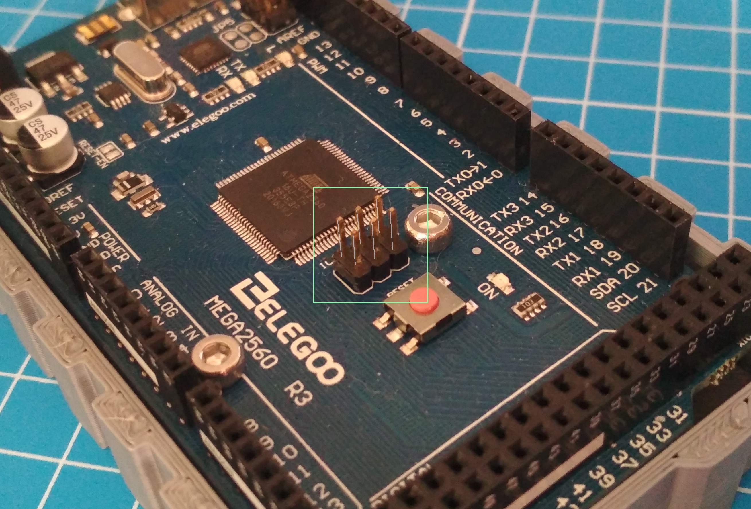
As mentioned earlier, we need to locate the correct
pins on the microcontroller to which to connect the pins on the USB ISP. Typically, if one was using an existing
manufactured development board, there would be a six-pin connector already connected to the board, with the pins
already wired to the correct pins on the microcontroller. Such a connector might look like this:
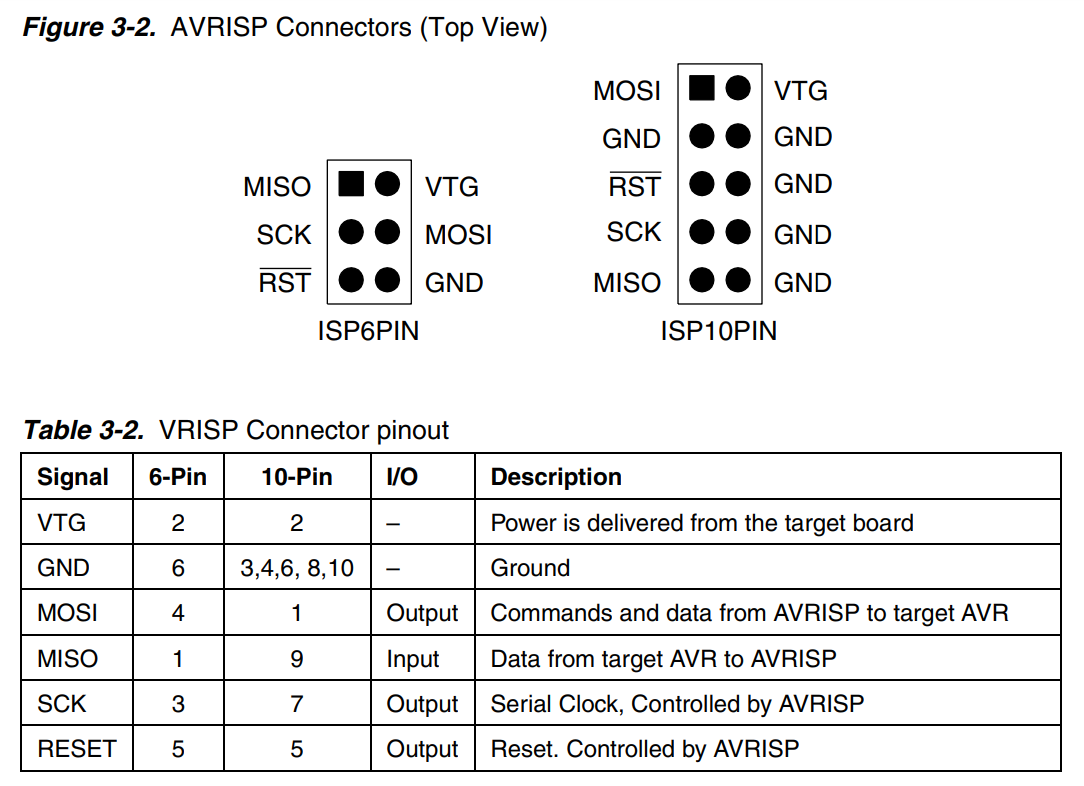
This kind of connector is typically attached to a ribbon cable that may have been supplied with the ISP. The
arrangement of the pins in the connector is specified in the
AVRISP User Guide, and all ISP programmers tend to be compatible with this. The pins on the
connector are described in the following diagram taken from the guide:
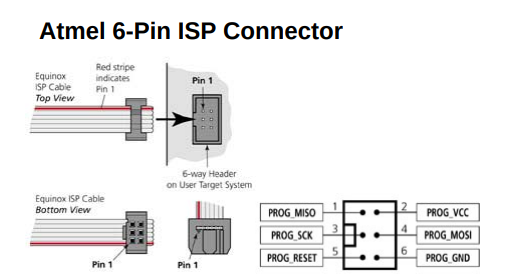
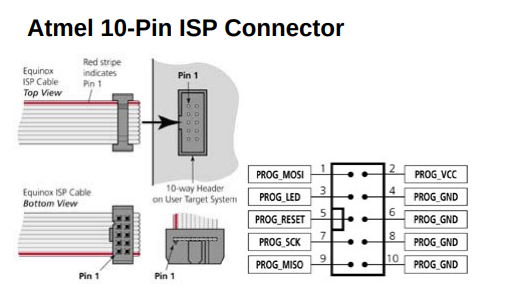
One needlessly frustrating aspect of this diagram is that although the pins are numbered, the diagram gives no
indication as to the orientation of the connector. A pair of diagrams taken from
avrfreaks
indicates that pin 3 is closest to the open side of the connector:
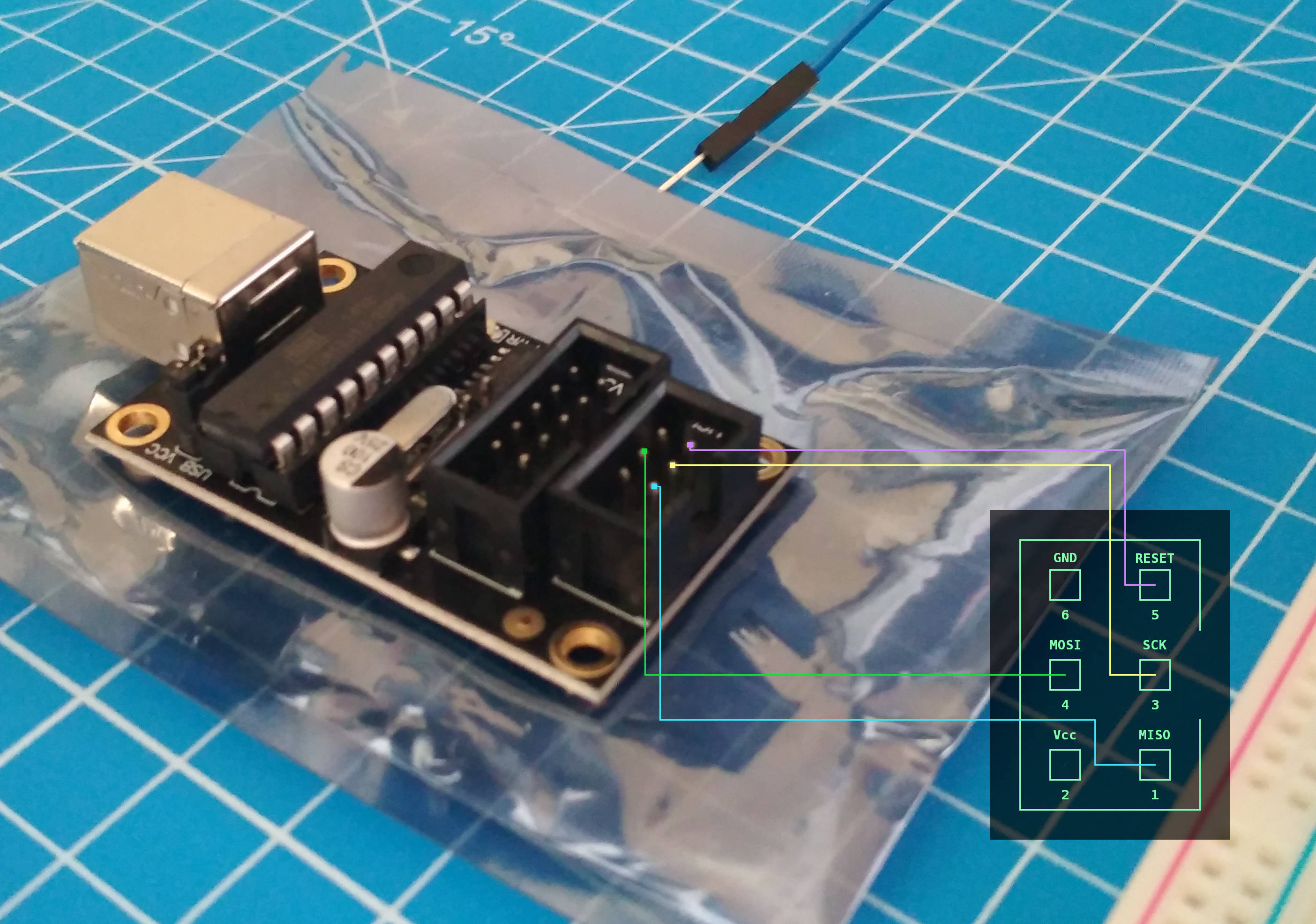
We need to connect the MOSI, MISO, SCK,
and RESET pins on the ISP to the corresponding pins on the microcontroller. We do not
need to connect the Vcc or GND pins as we will be relying on a
breadboard power supply to power the entire board. As such, this would also be a good time to connect a power
supply to the breadboard.
Looking back at the pin diagram for the
microcontroller, we can easily find the MOSI, MISO,
SCK, and RESET pins.
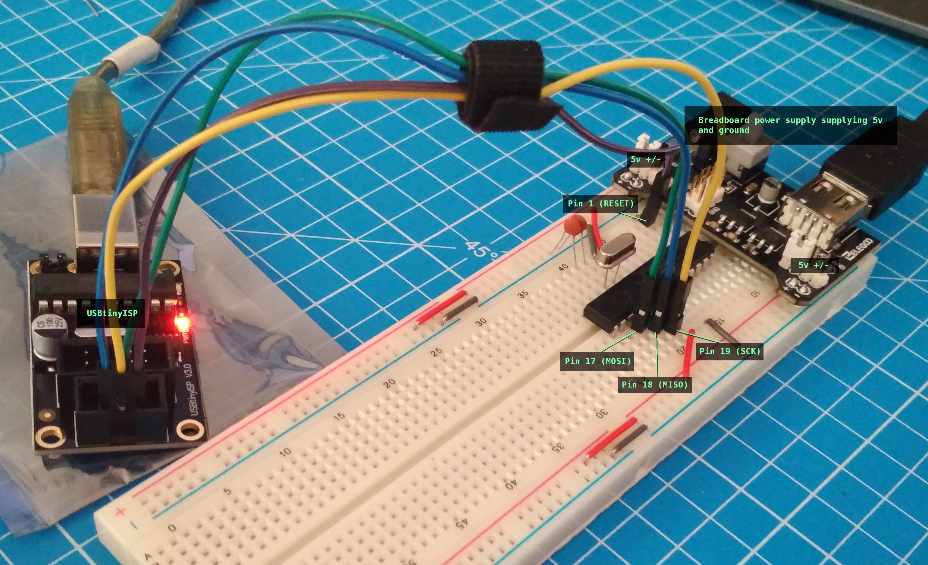
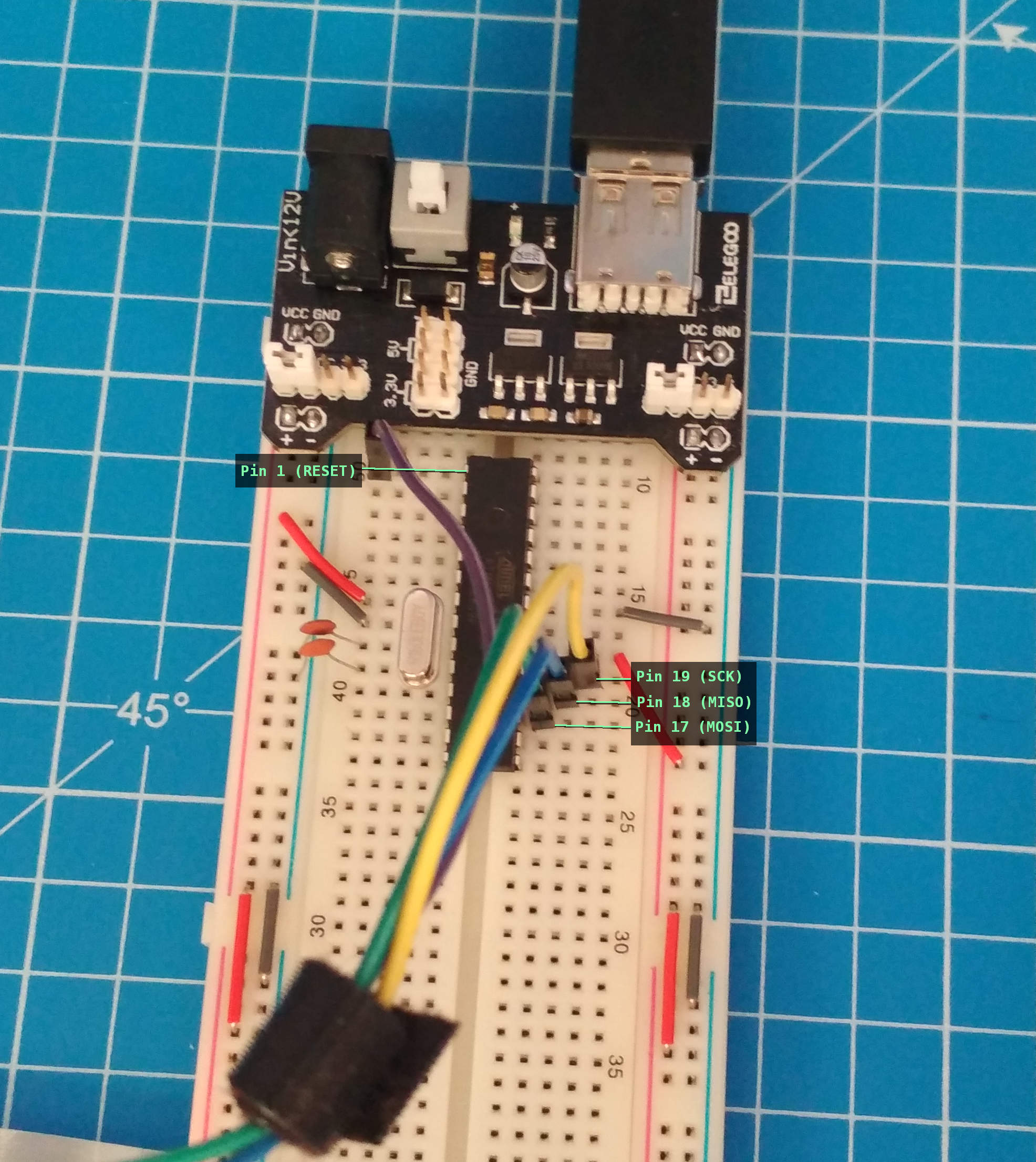
5.2.11. Connections
- Connect the breadboard power supply to the breadboard.
- Connect the MOSI pin of the ISP to pin 17 on the microcontroller.
- Connect the MISO pin of the ISP to pin 18 on the microcontroller.
- Connect the SCK pin of the ISP to pin 19 on the microcontroller.
- Connect the RESET pin of the ISP to pin 1 on the microcontroller.
All AVR microcontrollers have so-called fuse bits that can be programmed using an ISP.
The fuse bits are essentially software configuration bits that can be used to control, for example, whether the
chip will use an internal or external oscillator, or whether EEPROM values will be preserved across a chip erase
operation, or a large number of other configuration values. Fuse bits are stored in some kind of non-volatile
memory inside the controller, and the values set will survive indefinitely without a power supply. A good test
to determine whether we've wired up the chip correctly is to use an open-source command-line tool to attempt to
read the current values of the fuse bits using the ISP.
The command-line tool we'll be using is
avrdude
[1]. Most Linux distributions and the BSDs come with
precompiled packages of avrdude, so install it using whatever mechanism is
appropriate for your system. The avrdude tool knows how to send all of the commands
necessary to program an AVR microcontroller using a wide range of different programmers. The
avrdude
refers to the USBtinyISP programmer we're using as
usbtiny, but you might find whatever programmer you're using on the list of programmers that can be
viewed by executing avrdude -c ?:
5.3.3. Supported Programmers
$ avrdude -c ?

Valid programmers are:
  2232HIO          = FT2232H based generic programmer
  4232h            = FT4232H based generic programmer
  89isp            = Atmel at89isp cable
  abcmini          = ABCmini Board, aka Dick Smith HOTCHIP
  alf              = Nightshade ALF-PgmAVR, http://nightshade.homeip.net/
  arduino          = Arduino
  arduino-ft232r   = Arduino: FT232R connected to ISP
  atisp            = AT-ISP V1.1 programming cable for AVR-SDK1 from <http://micro-research.co.th/>
  atmelice         = Atmel-ICE (ARM/AVR) in JTAG mode
  atmelice_dw      = Atmel-ICE (ARM/AVR) in debugWIRE mode
  atmelice_isp     = Atmel-ICE (ARM/AVR) in ISP mode
  atmelice_pdi     = Atmel-ICE (ARM/AVR) in PDI mode
  avr109           = Atmel AppNote AVR109 Boot Loader
  avr910           = Atmel Low Cost Serial Programmer
  avr911           = Atmel AppNote AVR911 AVROSP
  avrftdi          = FT2232D based generic programmer
  avrisp           = Atmel AVR ISP
  avrisp2          = Atmel AVR ISP mkII
  avrispmkII       = Atmel AVR ISP mkII
  avrispv2         = Atmel AVR ISP V2
  bascom           = Bascom SAMPLE programming cable
  blaster          = Altera ByteBlaster
  bsd              = Brian Dean's Programmer, http://www.bsdhome.com/avrdude/
  buspirate        = The Bus Pirate
  buspirate_bb     = The Bus Pirate (bitbang interface, supports TPI)
  butterfly        = Atmel Butterfly Development Board
  butterfly_mk     = Mikrokopter.de Butterfly
  bwmega           = BitWizard ftdi_atmega builtin programmer
  C232HM           = FT232H based module from FTDI and Glyn.com.au
  c2n232i          = serial port banging, reset=dtr sck=!rts mosi=!txd miso=!cts
  dapa             = Direct AVR Parallel Access cable
  dasa             = serial port banging, reset=rts sck=dtr mosi=txd miso=cts
  dasa3            = serial port banging, reset=!dtr sck=rts mosi=txd miso=cts
  diecimila        = alias for arduino-ft232r
  dragon_dw        = Atmel AVR Dragon in debugWire mode
  dragon_hvsp      = Atmel AVR Dragon in HVSP mode
  dragon_isp       = Atmel AVR Dragon in ISP mode
  dragon_jtag      = Atmel AVR Dragon in JTAG mode
  dragon_pdi       = Atmel AVR Dragon in PDI mode
  dragon_pp        = Atmel AVR Dragon in PP mode
  dt006            = Dontronics DT006
  ere-isp-avr      = ERE ISP-AVR <http://www.ere.co.th/download/sch050713.pdf>
  flip1            = FLIP USB DFU protocol version 1 (doc7618)
  flip2            = FLIP USB DFU protocol version 2 (AVR4023)
  frank-stk200     = Frank STK200
  ft232r           = FT232R Synchronous BitBang
  ft245r           = FT245R Synchronous BitBang
  futurlec         = Futurlec.com programming cable.
  jtag1            = Atmel JTAG ICE (mkI)
  jtag1slow        = Atmel JTAG ICE (mkI)
  jtag2            = Atmel JTAG ICE mkII
  jtag2avr32       = Atmel JTAG ICE mkII im AVR32 mode
  jtag2dw          = Atmel JTAG ICE mkII in debugWire mode
  jtag2fast        = Atmel JTAG ICE mkII
  jtag2isp         = Atmel JTAG ICE mkII in ISP mode
  jtag2pdi         = Atmel JTAG ICE mkII PDI mode
  jtag2slow        = Atmel JTAG ICE mkII
  jtag3            = Atmel AVR JTAGICE3 in JTAG mode
  jtag3dw          = Atmel AVR JTAGICE3 in debugWIRE mode
  jtag3isp         = Atmel AVR JTAGICE3 in ISP mode
  jtag3pdi         = Atmel AVR JTAGICE3 in PDI mode
  jtagkey          = Amontec JTAGKey, JTAGKey-Tiny and JTAGKey2
  jtagmkI          = Atmel JTAG ICE (mkI)
  jtagmkII         = Atmel JTAG ICE mkII
  jtagmkII_avr32   = Atmel JTAG ICE mkII im AVR32 mode
  lm3s811          = Luminary Micro LM3S811 Eval Board (Rev. A)
  mib510           = Crossbow MIB510 programming board
  mkbutterfly      = Mikrokopter.de Butterfly
  nibobee          = NIBObee
  o-link           = O-Link, OpenJTAG from www.100ask.net
  openmoko         = Openmoko debug board (v3)
  pavr             = Jason Kyle's pAVR Serial Programmer
  pickit2          = MicroChip's PICkit2 Programmer
  picoweb          = Picoweb Programming Cable, http://www.picoweb.net/
  pony-stk200      = Pony Prog STK200
  ponyser          = design ponyprog serial, reset=!txd sck=rts mosi=dtr miso=cts
  siprog           = Lancos SI-Prog <http://www.lancos.com/siprogsch.html>
  sp12             = Steve Bolt's Programmer
  stk200           = STK200
  stk500           = Atmel STK500
  stk500hvsp       = Atmel STK500 V2 in high-voltage serial programming mode
  stk500pp         = Atmel STK500 V2 in parallel programming mode
  stk500v1         = Atmel STK500 Version 1.x firmware
  stk500v2         = Atmel STK500 Version 2.x firmware
  stk600           = Atmel STK600
  stk600hvsp       = Atmel STK600 in high-voltage serial programming mode
  stk600pp         = Atmel STK600 in parallel programming mode
  ttl232r          = FTDI TTL232R-5V with ICSP adapter
  tumpa            = TIAO USB Multi-Protocol Adapter
  UM232H           = FT232H based module from FTDI and Glyn.com.au
  uncompatino      = uncompatino with all pairs of pins shorted
  usbasp           = USBasp, http://www.fischl.de/usbasp/
  usbasp-clone     = Any usbasp clone with correct VID/PID
  usbtiny          = USBtiny simple USB programmer, http://www.ladyada.net/make/usbtinyisp/
  wiring           = Wiring
  xil              = Xilinx JTAG cable
  xplainedmini     = Atmel AVR XplainedMini in ISP mode
  xplainedmini_dw  = Atmel AVR XplainedMini in debugWIRE mode
  xplainedpro      = Atmel AVR XplainedPro in JTAG mode
We need to tell avrdude what kind of microcontroller we're using so that it knows
what programming commands to send. In this case, we're using an
atmega328p. We can now put all of this together and execute a command to read the
current fuse bit values on the microcontroller. Ensure that your programmer is connected, and that the
breadboard power supply is switched on, and execute the following command:
5.3.5. Supported Programmers
$ avrdude -c usbtiny -p atmega328p
avrdude: AVR device initialized and ready to accept instructions
Reading | ################################################## | 100% 0.01s
avrdude: Device signature = 0x1e950f (probably m328p)
avrdude: safemode: Fuses OK (E:FF, H:D9, L:62)
avrdude done.  Thank you.
If we take a look at the datasheet, we can see that the fuse bits are divided up into
extended, high, and
low
fuse bits. The default values for the fuse bits are given on pages 292 and 293 (the table for the extended fuse
is not reproduced here for reasons of brevity):
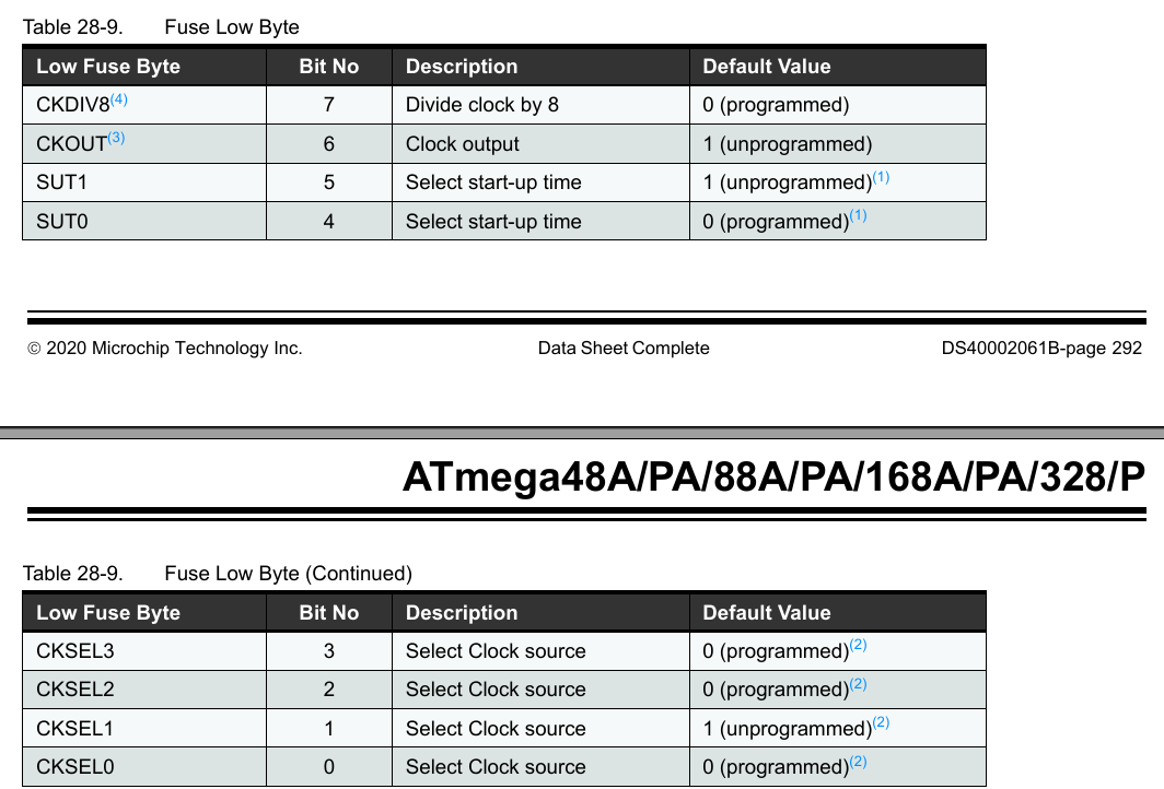
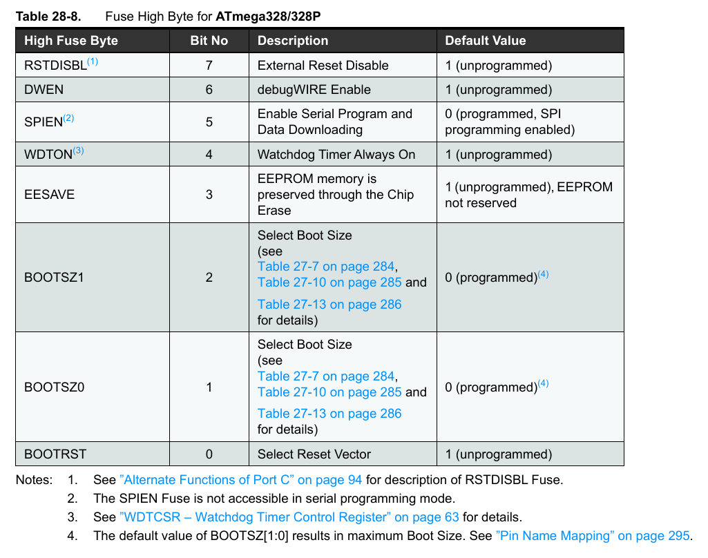
We can see that the default values for the extended, high, and low fuses are
0b11111111 (0xff), 0b11011001 (0xd9), and
0b01100010 (0x62), respectively. We can see that matches the values returned by
avrdude
and therefore we can be confident that both the programmer and the chip are working correctly.
As mentioned earlier, the ATMega328p chip is
configured by default to use an internal 8mhz oscillator effectively reduced to 1mhz. We've connected an
external 16mhz oscillator crystal and therefore we need to set some fuse bits in order to tell the
microcontroller to actually use it. The information on this in the datasheet is, to say the least, arduous.
Working through the "System Clock and Clock Options" section of the datasheet, starting on page 36, our first
task is to disable the clock divider so that our 16mhz external clock isn't reduced to 2mhz. We quickly reach
the following paragraph:
"The device is shipped with internal RC oscillator at 8.0MHz and with the fuse CKDIV8 programmed, resulting in
1.0MHz system clock. The startup time is set to maximum and time-out period enabled. (CKSEL = "0010", SUT =
"10", CKDIV8 = "0"). The default setting ensures that all users can make their desired clock source setting
using any available programming interface."
Therefore, we need to set the CKDIV8 bit to 1. Somewhat
counter-intuitively, fuse bits are considered "enabled" or "programmed" if they are set to
0, and "unprogrammed" or "disabled" if they are set to
1. Searching the datasheet for CKDIV8 eventually leads us
back to page 292 where we can see that bit 7 of the low fuse is the
CKDIV8
bit and is set to 0 (enabled) by default. Fuse values cannot be programmed
one bit at a time; it's necessary to set all eight bits of a given fuse in a single operation. We therefore need
to know what all of the bits are going to be before we can set them. We at least now know that our final low
fuse value will have to be
0b1???????, where ? indicates not-yet-known values.
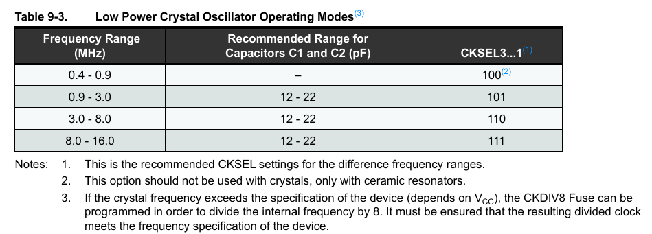
Next, we need to tell the microcontroller to actually use our external clock. Looking back at page 37 of the
datasheet, we can see that there are four "clock select" bits named CKSEL0,
CKSEL1, CKSEL2, and CKSEL3. We happen to
be using a 16mhz low power crystal oscillator, and we can see from the table that we
should set CKSEL1..3 to 0b111:
We're also required to set the start-up time. This is required because some types of oscillators and clocks take
longer than other types to stabilize and output a consistent pulse rate. There appear to be no downsides to
picking the most conservative (highest) values, which in this case means a 14 tick + 65 millisecond delay when
resetting the microcontroller. We can see from the table that we need to set the two "start up time" bits,
SUT0
and SUT1, and the remaining
CKSEL0
bit to 0b11 and 0b1, respectively.
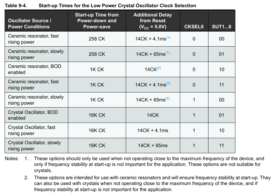
Putting all of this together, we have CKSEL0..3 = 0b1111,
SUT0..1 = 0b11, CKDIV8 = 0b1, which leaves only
one remaining bit in the low fuse value: CKOUT. The purpose of the
CKOUT
bit is to instruct the microcontroller to output the clock pulse it is receiving on a separate pin. We have no
use for this, and therefore CKOUT = 0b1. This, somewhat anti-climactically given
the amount of datasheet scanning it took to get here, means that our resulting low fuse value will
be 0b11111111. We can instruct
avrdude
to set this value:
5.4.9. Setting The Low Fuse
$ avrdude -c usbtiny -p atmega328p -U lfuse:w:0xff:m
avrdude: AVR device initialized and ready to accept instructions
Reading | ################################################## | 100% 0.01s

avrdude: Device signature = 0x1e950f (probably m328p)
avrdude: reading input file "0xff"
avrdude: writing lfuse (1 bytes):
Writing | ################################################## | 100% 0.00s

avrdude: 1 bytes of lfuse written
avrdude: verifying lfuse memory against 0xff:
avrdude: load data lfuse data from input file 0xff:
avrdude: input file 0xff contains 1 bytes
avrdude: reading on-chip lfuse data:
Reading | ################################################## | 100% 0.00s

avrdude: verifying ...
avrdude: 1 bytes of lfuse verified
avrdude: safemode: Fuses OK (E:FF, H:D9, L:FF)

avrdude done.  Thank you.
The -U lfuse:w:0xff:m option specifies that we want to perform a write operation
(w) on the low fuse value (lfuse), and we want to
specify an immediate value (m) of 0xff. It's also
possible to read values from files if the m flag is not used.