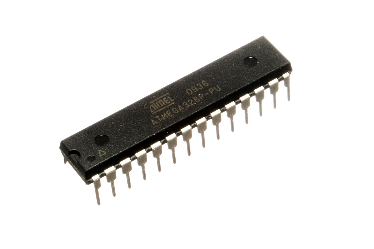
The first step required is to insert the microcontroller onto the breadboard. In the datasheet, on page 12, we
find a diagram of the pin configuration for the dual in-line package form of the chip:
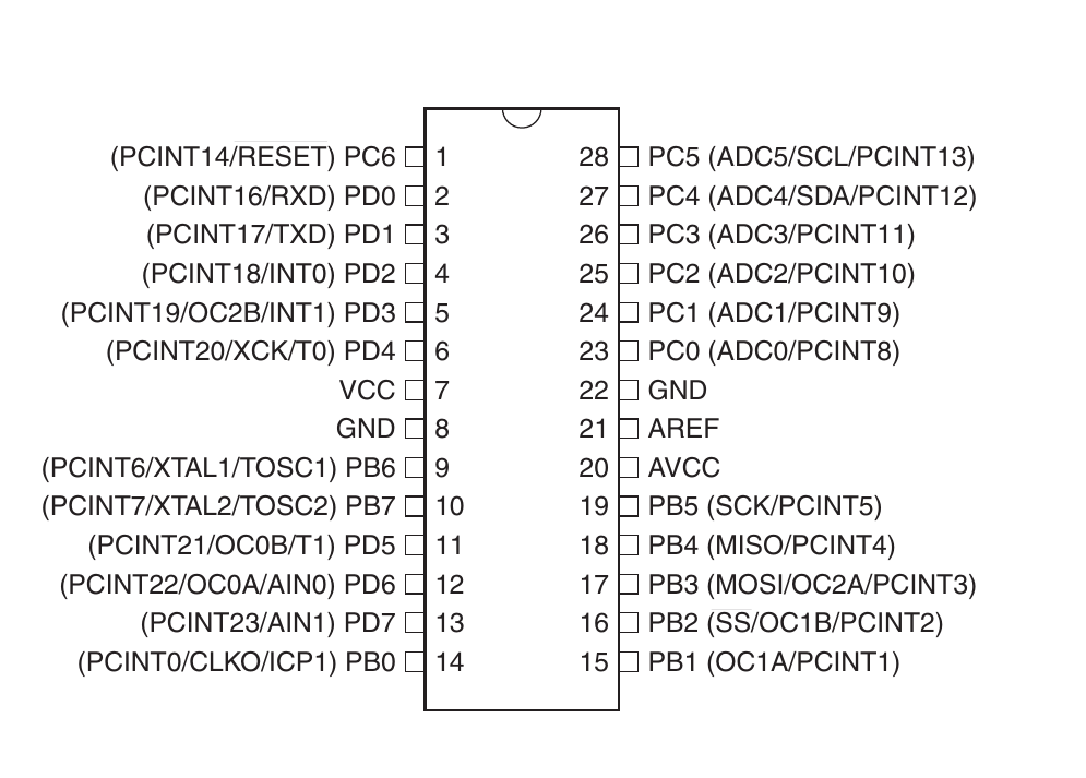
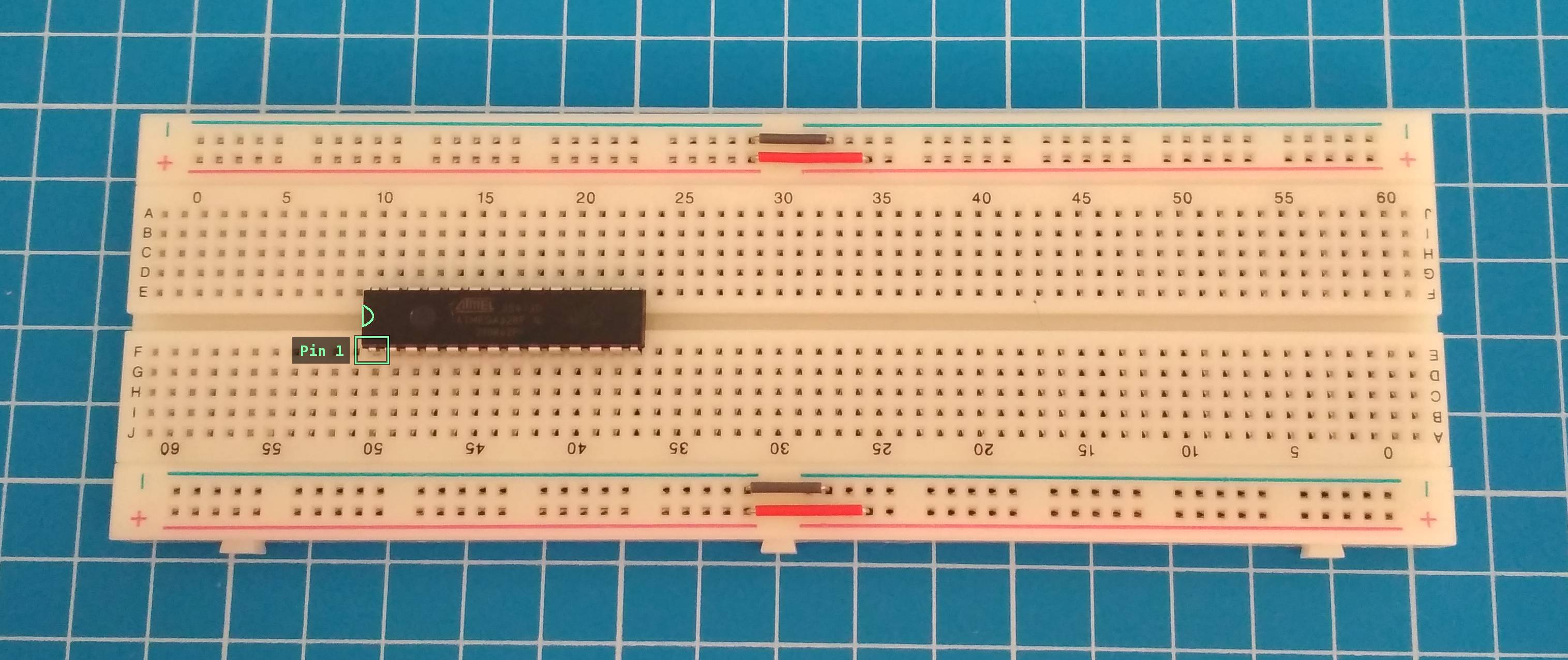
The chip features a small indentation at one end, and a small dot next to Pin 1. It doesn't matter how we orient
the chip in the breadboard as long as we understand where Pin 1 is; if we can locate that pin, we can follow the
pins counter-clockwise around the chip to locate any other numbered pin. It's common practice to insert dual
in-line package chips across the center divider in a given breadboard, as this allows for the row of pins on one
side of the chip to be electrically disconnected from the row on the other side.
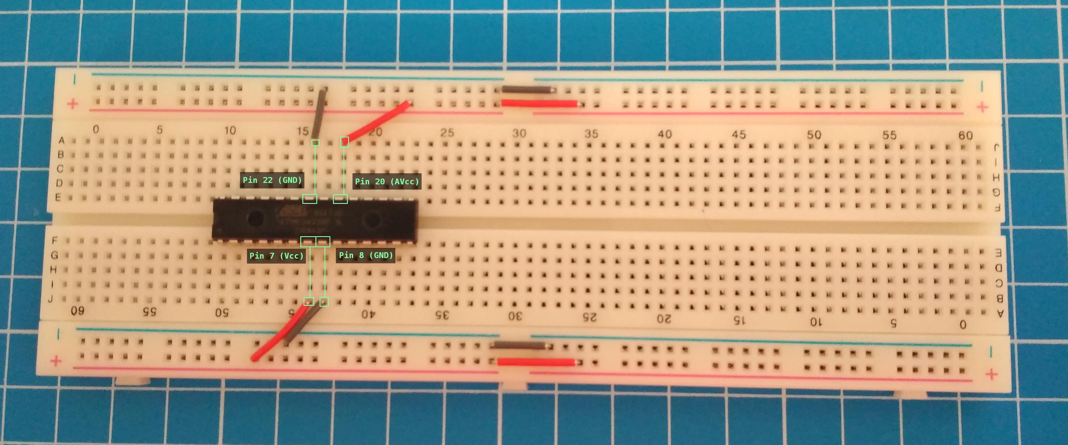
On page 13, the datasheet indicates that we need to connect the IC to a voltage source, and also to ground.
Specifically, it indicates that the Vcc pin must be connected to a voltage source, and
also that the AVcc pin "should be externally connected to Vcc, even
if the ADC is not used."
The datasheet also indicates that the AVcc pin should be connected to the voltage
source via some kind of low-pass filter if the ADC functionality in the microcontroller is going to be used
[1]. Because the circuit in this example will not be
making use of an ADC, this pin can be safely connected directly to the voltage source without using a filter.
4.2.2. Connections
- Connect pin 7 to the breadboard 5V rail.
- Connect pin 8 to the breadboard ground rail.
- Connect pin 22 to the breadboard ground rail.
- Connect pin 20 to the breadboard 5V rail.
By default, ATMega328p chips are configured to use an internal 8mhz oscillator. The chip is factory configured
to divide the ticks of the internal oscillator by 8, yielding a configuration that runs the chip at 1mhz. We,
however, want to run the chip at a higher clock speed of 16mhz, and therefore need to connect an external
oscillator crystal.
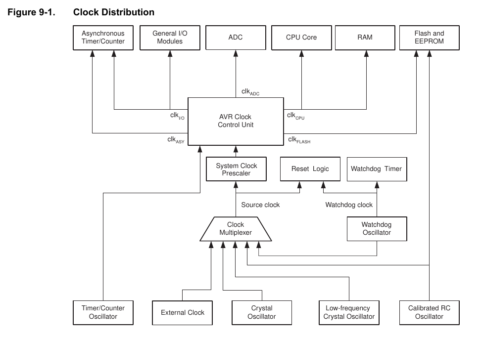
Page 36 of the datasheet indicates how all of the various system clocks are derived:
Pages 39 and 40 of the datasheet indicate that we can't just connect an oscillator directly to the chip; we must
include a pair of capacitors it refers to as C1 and
C2. The reason for this, as ever, is noise: If a circuit is very noisy, then small
spikes of noise could be misinterpreted as oscillator pulses, yielding a system clock that behaves erratically.
The datasheet gives suggested values for ceramic capacitors for a 16mhz clock, and we're using the highest
suggested values of 22pF. The datasheet indicates that the oscillator should be
connected with two capacitors in parallel, and also connected to ground:
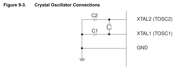
Looking back at the pin diagram, we can see that the
two clock pins, XTAL1 and XTAL2, are on pins 9 and 10,
respectively. Neither the crystal oscillator or the ceramic capacitors are
polarized
components, so don't be concerned about inserting them the wrong way round; they can be inserted in any
orientation.
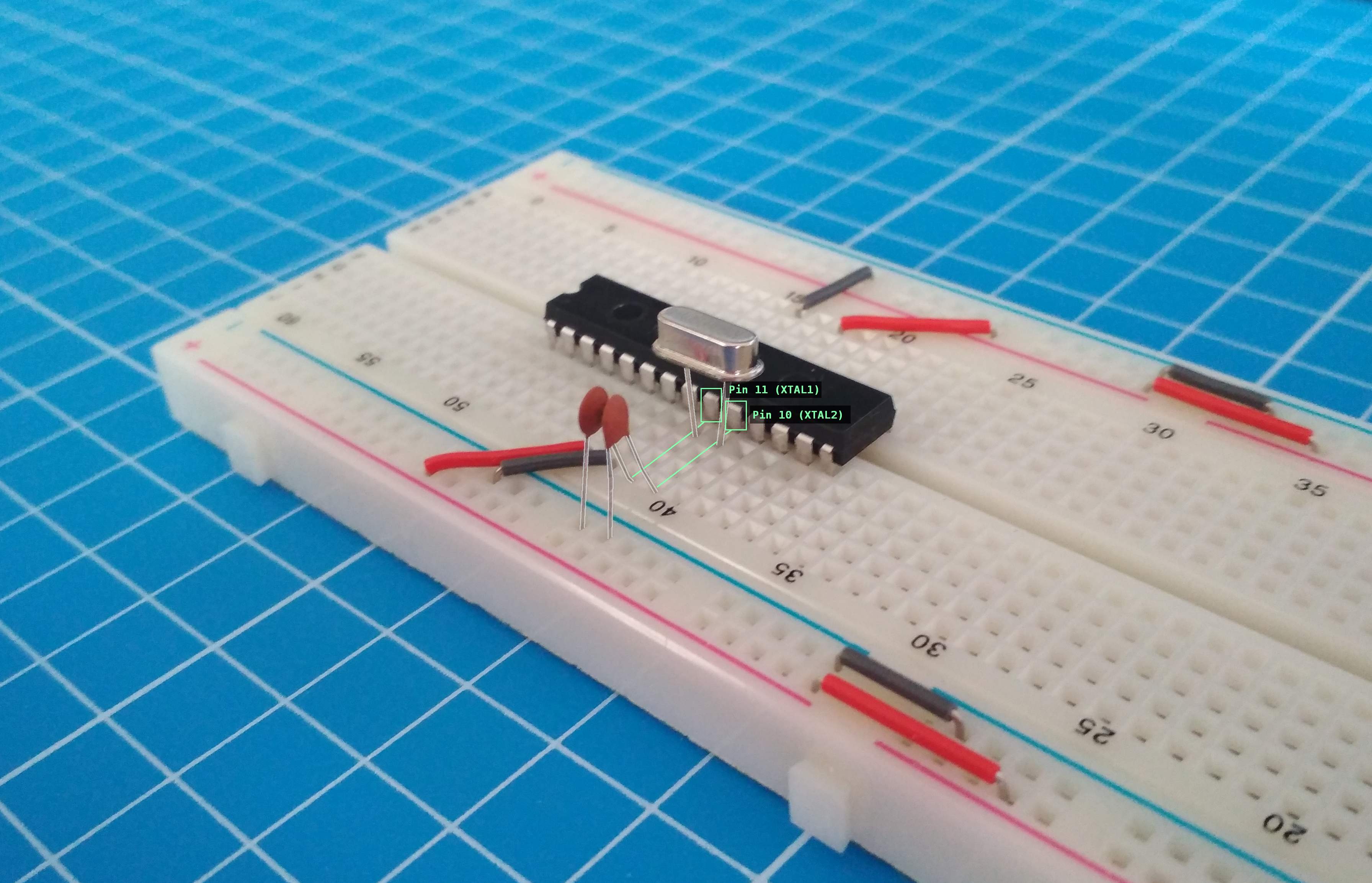
4.3.7. Connections
- Connect the two pins of the crystal oscillator to pins 9 and 10.
- Connect C1 to pin 9 and to the breadboard ground rail.
- Connect C2 to pin 10 and to the breadboard ground rail.
At this point, it might be surprising to learn that this is actually all that's required to run the chip. If we
were to supply voltage at this point, the microcontroller would power up and would begin executing code. The
problem, obviously, is that the microcontroller doesn't contain any code. The next step, therefore, is to set up
the programmer required to actually get code onto the chip.