In the previous section, we put together a working
Blink program using assembler. However, the program has a number of limitations:
7.1.2. Limitations
- The program requires a lot of setup code. Roughly 50% of the actual assembler text has nothing to do with Blink.
- The program doesn't use any kind of accurate timer for pausing between toggling the LED on and off. It simply wastes execution time in a manner that's highly dependent on the microcontroller clock speed.
- The Blink program is usually accompanied by some kind of text debugging output that can be observed on a serial console or some similar connection when the program is running. Our Blink program doesn't do any of this.
Largely, the first problem can be eliminated by writing the program in C and allowing the compiler to generate
its own platform initialization code. Essentially, we'll allow the compiler to generate
__avr_interrupt_vectors
and
__avr_setup
for us. We can inspect the generated code as a learning exercise to see if there's anything in the
compiler-generated version that differs from our own.
The second problem can be eliminated by using the dedicated timer hardware present on the microcontroller.
The third problem can be eliminated by using the
USART
hardware included on the microcontroller to provide output that can be observed using a serial console.
We'll fix each problem one at a time, yielding a final program that has accurate timing and produces debugging
output.
Rewriting our original pause function in C is
trivial, as we actually specified it in C
originally
and then wrote the assembler version. However, rewriting the code that actually
toggles the LED
is somewhat more difficult, because we don't have direct access to the out instruction
required to write to addresses in I/O space.
Thankfully, there's a solution to this. Page 30 of the datasheet has this to say:
"When using the I/O specific commands IN and OUT, the I/O addresses 0x00 - 0x3F must be used. When addressing
I/O Registers as data space using LD and ST instructions, 0x20 must be added to these addresses."
What the data sheet is implicitly stating is that the registers in I/O space are also accessible in data space
at addresses 32 bytes higher. This can be observed directly if we turn once again to the
register summary
on page 624, we can see that, for example the address of PORTB is
io@0x05
and data@0x25. This means that we can actually access these registers using
volatile uint8_t
pointers in C. The pointers must be volatile because
reading or writing to the target addresses produces I/O effects and the compiler must not be allowed to omit or
reorder those operations for the purposes of optimization.
Given all of this information, we can trivially rewrite the Blink program in C to be behaviour-compatible with
the assembler version:
7.2.6. Blink In C Poorly
#include <stdint.h>

void
pause (void)
{
  for (volatile uint8_t z = 0; z < 100; ++z) {
    for (volatile uint8_t y = 0; y < 100; ++y) {
      for (volatile uint8_t z = 0; z < 100; ++z) {
        // Do nothing
      }
    }
  }
}

volatile uint8_t * const PORTB = (volatile uint8_t *) 0x0025;
volatile uint8_t * const DDRB = (volatile uint8_t *) 0x0024;

int
main (void)
{
  *DDRB = 1;

  for (;;) {
    *PORTB = 1;
    pause();
    *PORTB = 0;
    pause();
  }
}
Assuming that we placed the code into a file called blinkBad.c, we can compile the
program with minimal optimization:
7.2.8. Blink In C Poorly
$ avr-gcc -Os -mmcu=atmega328p -o blinkBad blinkBad.c
$ avr-objcopy -j .text -j .data -O ihex blinkBad blinkBad.hex
We can use the avr-objdump tool to disassemble the executable and view the resulting
machine code:
7.2.10. Blink In C Object Code
$ avr-objdump -d blinkBad

blinkBad:     file format elf32-avr


Disassembly of section .text:

00000000 <__vectors>:
   0:	0c 94 34 00 	jmp	0x68	; 0x68 <__ctors_end>
   4:	0c 94 49 00 	jmp	0x92	; 0x92 <__bad_interrupt>
   8:	0c 94 49 00 	jmp	0x92	; 0x92 <__bad_interrupt>
   c:	0c 94 49 00 	jmp	0x92	; 0x92 <__bad_interrupt>
  10:	0c 94 49 00 	jmp	0x92	; 0x92 <__bad_interrupt>
  14:	0c 94 49 00 	jmp	0x92	; 0x92 <__bad_interrupt>
  18:	0c 94 49 00 	jmp	0x92	; 0x92 <__bad_interrupt>
  1c:	0c 94 49 00 	jmp	0x92	; 0x92 <__bad_interrupt>
  20:	0c 94 49 00 	jmp	0x92	; 0x92 <__bad_interrupt>
  24:	0c 94 49 00 	jmp	0x92	; 0x92 <__bad_interrupt>
  28:	0c 94 49 00 	jmp	0x92	; 0x92 <__bad_interrupt>
  2c:	0c 94 49 00 	jmp	0x92	; 0x92 <__bad_interrupt>
  30:	0c 94 49 00 	jmp	0x92	; 0x92 <__bad_interrupt>
  34:	0c 94 49 00 	jmp	0x92	; 0x92 <__bad_interrupt>
  38:	0c 94 49 00 	jmp	0x92	; 0x92 <__bad_interrupt>
  3c:	0c 94 49 00 	jmp	0x92	; 0x92 <__bad_interrupt>
  40:	0c 94 49 00 	jmp	0x92	; 0x92 <__bad_interrupt>
  44:	0c 94 49 00 	jmp	0x92	; 0x92 <__bad_interrupt>
  48:	0c 94 49 00 	jmp	0x92	; 0x92 <__bad_interrupt>
  4c:	0c 94 49 00 	jmp	0x92	; 0x92 <__bad_interrupt>
  50:	0c 94 49 00 	jmp	0x92	; 0x92 <__bad_interrupt>
  54:	0c 94 49 00 	jmp	0x92	; 0x92 <__bad_interrupt>
  58:	0c 94 49 00 	jmp	0x92	; 0x92 <__bad_interrupt>
  5c:	0c 94 49 00 	jmp	0x92	; 0x92 <__bad_interrupt>
  60:	0c 94 49 00 	jmp	0x92	; 0x92 <__bad_interrupt>
  64:	0c 94 49 00 	jmp	0x92	; 0x92 <__bad_interrupt>

00000068 <__ctors_end>:
  68:	11 24       	eor	r1, r1
  6a:	1f be       	out	0x3f, r1	; 63
  6c:	cf ef       	ldi	r28, 0xFF	; 255
  6e:	d8 e0       	ldi	r29, 0x08	; 8
  70:	de bf       	out	0x3e, r29	; 62
  72:	cd bf       	out	0x3d, r28	; 61

00000074 <__do_copy_data>:
  74:	11 e0       	ldi	r17, 0x01	; 1
  76:	a0 e0       	ldi	r26, 0x00	; 0
  78:	b1 e0       	ldi	r27, 0x01	; 1
  7a:	e6 ef       	ldi	r30, 0xF6	; 246
  7c:	f0 e0       	ldi	r31, 0x00	; 0
  7e:	02 c0       	rjmp	.+4      	; 0x84 <__do_copy_data+0x10>
  80:	05 90       	lpm	r0, Z+
  82:	0d 92       	st	X+, r0
  84:	a4 30       	cpi	r26, 0x04	; 4
  86:	b1 07       	cpc	r27, r17
  88:	d9 f7       	brne	.-10     	; 0x80 <__do_copy_data+0xc>
  8a:	0e 94 6f 00 	call	0xde	; 0xde <main>
  8e:	0c 94 79 00 	jmp	0xf2	; 0xf2 <_exit>

00000092 <__bad_interrupt>:
  92:	0c 94 00 00 	jmp	0	; 0x0 <__vectors>

00000096 <pause>:
  96:	cf 93       	push	r28
  98:	df 93       	push	r29
  9a:	00 d0       	rcall	.+0      	; 0x9c <pause+0x6>
  9c:	0f 92       	push	r0
  9e:	cd b7       	in	r28, 0x3d	; 61
  a0:	de b7       	in	r29, 0x3e	; 62
  a2:	1b 82       	std	Y+3, r1	; 0x03
  a4:	8b 81       	ldd	r24, Y+3	; 0x03
  a6:	84 36       	cpi	r24, 0x64	; 100
  a8:	30 f0       	brcs	.+12     	; 0xb6 <pause+0x20>
  aa:	0f 90       	pop	r0
  ac:	0f 90       	pop	r0
  ae:	0f 90       	pop	r0
  b0:	df 91       	pop	r29
  b2:	cf 91       	pop	r28
  b4:	08 95       	ret
  b6:	1a 82       	std	Y+2, r1	; 0x02
  b8:	8a 81       	ldd	r24, Y+2	; 0x02
  ba:	84 36       	cpi	r24, 0x64	; 100
  bc:	20 f0       	brcs	.+8      	; 0xc6 <pause+0x30>
  be:	8b 81       	ldd	r24, Y+3	; 0x03
  c0:	8f 5f       	subi	r24, 0xFF	; 255
  c2:	8b 83       	std	Y+3, r24	; 0x03
  c4:	ef cf       	rjmp	.-34     	; 0xa4 <pause+0xe>
  c6:	19 82       	std	Y+1, r1	; 0x01
  c8:	89 81       	ldd	r24, Y+1	; 0x01
  ca:	84 36       	cpi	r24, 0x64	; 100
  cc:	20 f0       	brcs	.+8      	; 0xd6 <pause+0x40>
  ce:	8a 81       	ldd	r24, Y+2	; 0x02
  d0:	8f 5f       	subi	r24, 0xFF	; 255
  d2:	8a 83       	std	Y+2, r24	; 0x02
  d4:	f1 cf       	rjmp	.-30     	; 0xb8 <pause+0x22>
  d6:	89 81       	ldd	r24, Y+1	; 0x01
  d8:	8f 5f       	subi	r24, 0xFF	; 255
  da:	89 83       	std	Y+1, r24	; 0x01
  dc:	f5 cf       	rjmp	.-22     	; 0xc8 <pause+0x32>

000000de <main>:
  de:	81 e0       	ldi	r24, 0x01	; 1
  e0:	84 b9       	out	0x04, r24	; 4
  e2:	c1 e0       	ldi	r28, 0x01	; 1
  e4:	c5 b9       	out	0x05, r28	; 5
  e6:	0e 94 4b 00 	call	0x96	; 0x96 <pause>
  ea:	15 b8       	out	0x05, r1	; 5
  ec:	0e 94 4b 00 	call	0x96	; 0x96 <pause>
  f0:	f9 cf       	rjmp	.-14     	; 0xe4 <main+0x6>

000000f2 <_exit>:
  f2:	f8 94       	cli

000000f4 <__stop_program>:
  f4:	ff cf       	rjmp	.-2      	; 0xf4 <__stop_program>
A number of similarities and differences stand out. Firstly, our original
__avr_interrupt_vectors
table is replaced with a compiler-generated version called __vectors which performs
largely the same tasks. Our __avr_setup function is
replaced with a compiler-generated version called __ctors_end that performs the
exact same tasks including clearing the status register and setting up the stack pointer. The execution of the
__ctors_end
function leads directly to a function called __do_copy_data that does not
correspond to anything we originally wrote in the assembler version of Blink. The purpose of this function is to
actually to support programming in C. Note that we mentioned
previously
that AVR uses multiple addresses spaces for code and data, whilst C programmers are accustomed to working
in a single address space on typical hardware architectures. The
__do_copy_data
function exists to copy data from the code space into the data space in order to initialize the values of any
variables defined in C. Without going into too much detail, the code uses the
lpm
instruction to copy a region of memory from code space into locations in data space. The compiler's linker
defines two symbols
__data_start
and __data_end that define the start and end addresses of the data in code space,
and the addresses of these symbols are inlined into the generated code of
__do_copy_data
and used to perform the copying operation. Given that there is very little to be learned by writing this code by
hand, and given that it only exists to support programming in C on the microcontroller, we're satisfied with
allowing the compiler to generate it.
Once the __do_copy_data function has completed, it performs an unconditional jump
to our main function. The object code generated for
main
is surprisingly almost identical to our assembler code. The reason that this is surprising is that we explicitly
decided to write to
PORTB
and DDRB using addresses in data space, but the compiler was intelligent enough to
translate this code to executing out instructions on addresses in I/O space!
The __do_copy_data also includes a jump to a generated
_exit
function that turns off all interrupts and then continues to a function called
__stop_program
that simply loops forever and does nothing. The purpose of these two functions is to "halt" the
microcontroller should the main function ever return.
Lastly, the code generated for the pause function was the largest difference. The
code is similar, but has been reorganized to execute the same algorithm but with more in the way of stack
manipulation, and with use of the ability to treat certain pairs of 8-bit registers as single 16-bit registers.
The differences here are only of interest to assembler programmers, and we won't bother to discuss them any
further.
Flashing the resulting blinkBad.hex file to the microcontroller with
avrdude
will result in an LED that blinks in the same manner as the assembler version, except that it will almost
certainly blink slightly more slowly due to the generated
pause
function implementation wasting more time than the pure assembler version.
The next step will be to use a hardware timer to precisely control the LED blink periods.
On page 120 of the datasheet, we can see that the ATMega328p comes equipped with a 16-bit timer unit. The timer
unit can act as a counter that ticks at a rate we specify, and we can choose to act
when the counter reaches whatever tick count we require. We'll use this timer to count out a period of one
second so that we can turn the LED on and off at a rate that is independent of the CPU clock speed.
The first part of configuring the timer on the microcontroller is determining the
clock prescaler value. The way the timer on the ATMega328p works is that it will tick
at a rate that is some division of the system clock. The datasheet refers to this
as CLKi/o. If the clock prescaler value is set to
1, then the clock will tick at a rate of
16mhz = 16000000hz / 1 = 16000000hz. If the clock prescaler value is set
to 8, then the clock will tick at a rate of
16000000hz / 8 = 8000000hz = 8mhz. If the clock prescaler value is set to
1024
then the clock will tick at a rate of
16000000hz / 1024 = 15625hz = 15.625khz. The prescaler value can only be set
to 1, 8, 64,
256, or 1024. Why would we pick one prescaler value
over another? The timer, as mentioned, is a 16-bit counter. Therefore it can only count
65535
ticks before it overflows. At 16mhz,
65535 / 16000000 ≈ 0.0040959375, meaning that we'd be able to count out
approximately 4ms before the timer overflowed. However, with the prescaler set
at 1024, we get
65535 / (16000000 / 1024) ≈ 4.19424. This means that we could count out
approximately four seconds before the timer overflowed. Larger prescaler values, however, make the clock less
precise. A 16mhz clock with no prescaling effectively counts individual periods of
1 / 16000000 ≈ 0.0000000625
seconds or
62.5
nanoseconds. A 16mhz clock with a prescaler of
1024, however, effectively counts individual periods of
1 / (16000000 / 1024) ≈ 0.000064
seconds or
64
microseconds. We trade the ability to measure smaller slices of time, for the ability to measure longer overall
periods before the timer overflows. Given that our blink program works in periods of one second, and that we
don't care about millisecond precision, we can safely use a prescaler value of 1024.
The prescaler value is specified using the lowest 3 bits of the TCCR1B register as
described on pages 142 and 143. We want to use a value of 0b101 to select a
1024
prescaler. All of the other bits in the register can be left at 0.
The second part of configuring the timer simply involves initializing the counter to a known initial value. On
page 143 of the datasheet, the 16-bit timer value is exposed using a pair of 8-bit registers
TCNT1H
and TCNT1L, containing the high and low 8 bits of the 16-bit counter, respectively.
We can simply initialize these to
0
every time we want to start counting, but the datasheet does specify on page 122 that:
7.3.4. 16-bit Register Access
- When writing to a 16-bit register, we must write the high byte followed by the low byte.
- When reading from a 16-bit register, we must read the low byte followed by the high byte.
As long as we take care to get the order of operations right, there won't be any problems.
Turning once again to the register summary on page 622, we can see that the
TCCR1B
register is an 8-bit register at data@0x0081,
TCNT1H
is an 8-bit register at
data@0x0085, and TCNT1L is an 8-bit register
at data@0x0084. We can therefore use the rather unsurprising declarations in C to
access them:
7.3.7. Timer Registers
volatile uint8_t * const TCCR1B = (volatile uint8_t *) 0x0081;
volatile uint8_t * const TCNT1L = (volatile uint8_t *) 0x0084;
volatile uint8_t * const TCNT1H = (volatile uint8_t *) 0x0085;
We can select a prescaler and initialize the counter with the following equally unsurprising statements:
7.3.9. Timer Register Configuration
// Select a /1024 prescaler.
  *TCCR1B = 0b00000101;
  *TCNT1H = 0;
  *TCNT1L = 0;
Note that we're careful to write the high byte of the counter first, followed by the low byte of the counter.
Now, we simply need to sit in a loop, checking the counter on every iteration to see if the desired number of
ticks has elapsed. How many ticks do we need to count out one second? Remember that with a
1024
prescaler at 16000000hz,
1 / (16000000 / 1024) ≈ 0.000064
seconds, so we need
1 / 0.000064 = 15625
ticks to make one second. Writing the
pause
function is now straightforward, and we can fill in the entirety of the improved Blink program.
7.3.12. Blink Better
#include <stdint.h>

volatile uint8_t * const TCCR1B = (volatile uint8_t *) 0x0081;
volatile uint8_t * const TCNT1L = (volatile uint8_t *) 0x0084;
volatile uint8_t * const TCNT1H = (volatile uint8_t *) 0x0085;

static const uint16_t ticks_per_second = 15625;

void
pause (void)
{
  // Select a /1024 prescaler.
  *TCCR1B = 0b00000101;
  *TCNT1H = 0;
  *TCNT1L = 0;

  for (;;) {
    uint16_t time = 0;
    time |= *TCNT1L;
    time |= *TCNT1H << 8;

    if (time >= ticks_per_second) {
      return;
    }
  }
}

volatile uint8_t * const PORTB = (volatile uint8_t *) 0x0025;
volatile uint8_t * const DDRB = (volatile uint8_t *) 0x0024;

int
main (void)
{
  *DDRB = 1;

  for (;;) {
    *PORTB = 1;
    pause();
    *PORTB = 0;
    pause();
  }
}
An even better version of this program would define a function that takes the microcontroller speed in hz, and
the prescaler value, and returns the number of ticks required for one second. This function would be called at
run-time rather than hardcoding a value of 15625 ticks. This is left as an exercise
for the reader!
The last part of the improved Blink program will be to produce output from the program that can be observed on a
serial console. This will require both hardware and software components to achieve.
The ATMega328p has dedicated hardware for sending and receiving data using the
USART
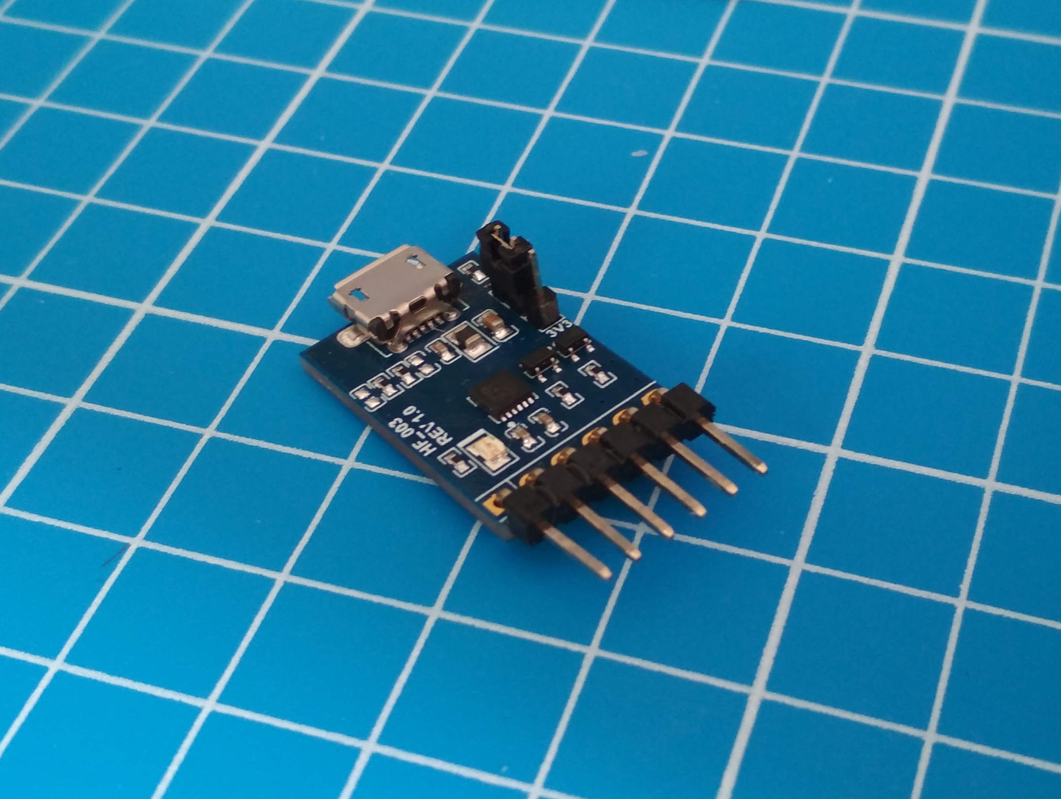
protocol. Additionally, there are extremely inexpensive USB ↔ USART adapters available. The adapter specified in
the bill of materials is the
FTDI LC234X, and is actually sold as
a development board in order to demonstrate the capabilities of the onboard
FT234XD
IC. Any USB ↔ USART adapter will work, but you'll need to adapt the instructions here slightly when it comes to
actually physically connecting the device. The approach we're going to take is to have the ATMega328p print
messages over a USART connection, and use a USB ↔ USART adapter to allow an ordinary Linux/BSD workstation to
access the adapter as a serial console. We can actually use this connection to both send and receive data to and
from the microcontroller, but we'll only use it in a receiving capacity on the workstation side for this book.
As usual, we're faced with the problem of working which pins must be connected. Consulting the
pin diagram
for the ATMega328p shows that pin 2 is the RXD pin for the USART, and pin 3 is the
TXD. The terms RXD and
TXD
were found by reading the section of the datasheet on the USART on page 179. The USART protocol actually
dictates that the RXD pin on the sending device must be connected to the
TXD
pin on the receiver, and vice versa.
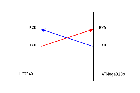
Given this information, connecting the device to the breadboard is straightforward.
7.4.7. Connections
- Connect the TXD pin on the LC234X to pin 2 on the ATMega328p.
- Connect the RXD pin on the LC234X to pin 3 on the ATMega328p.
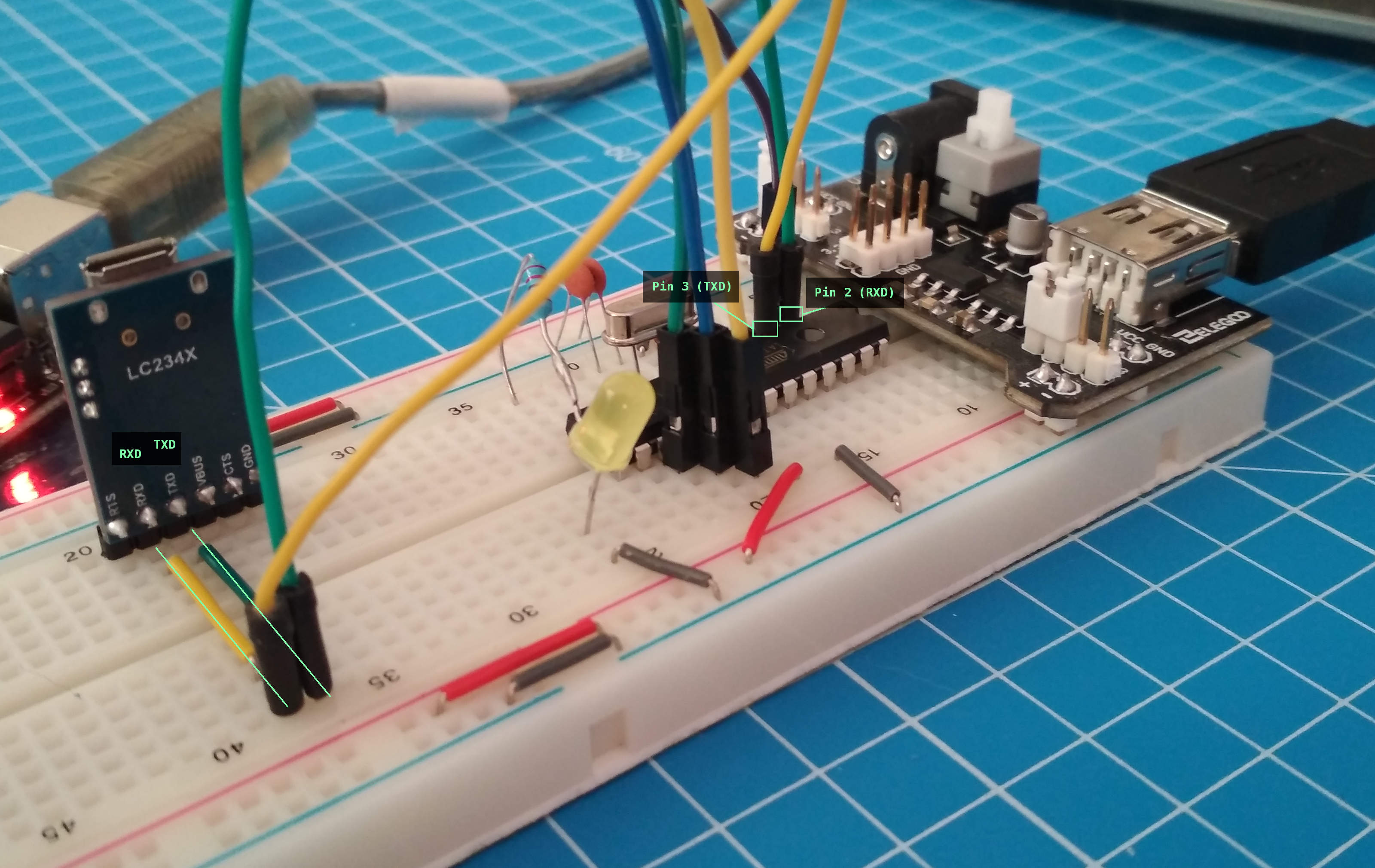
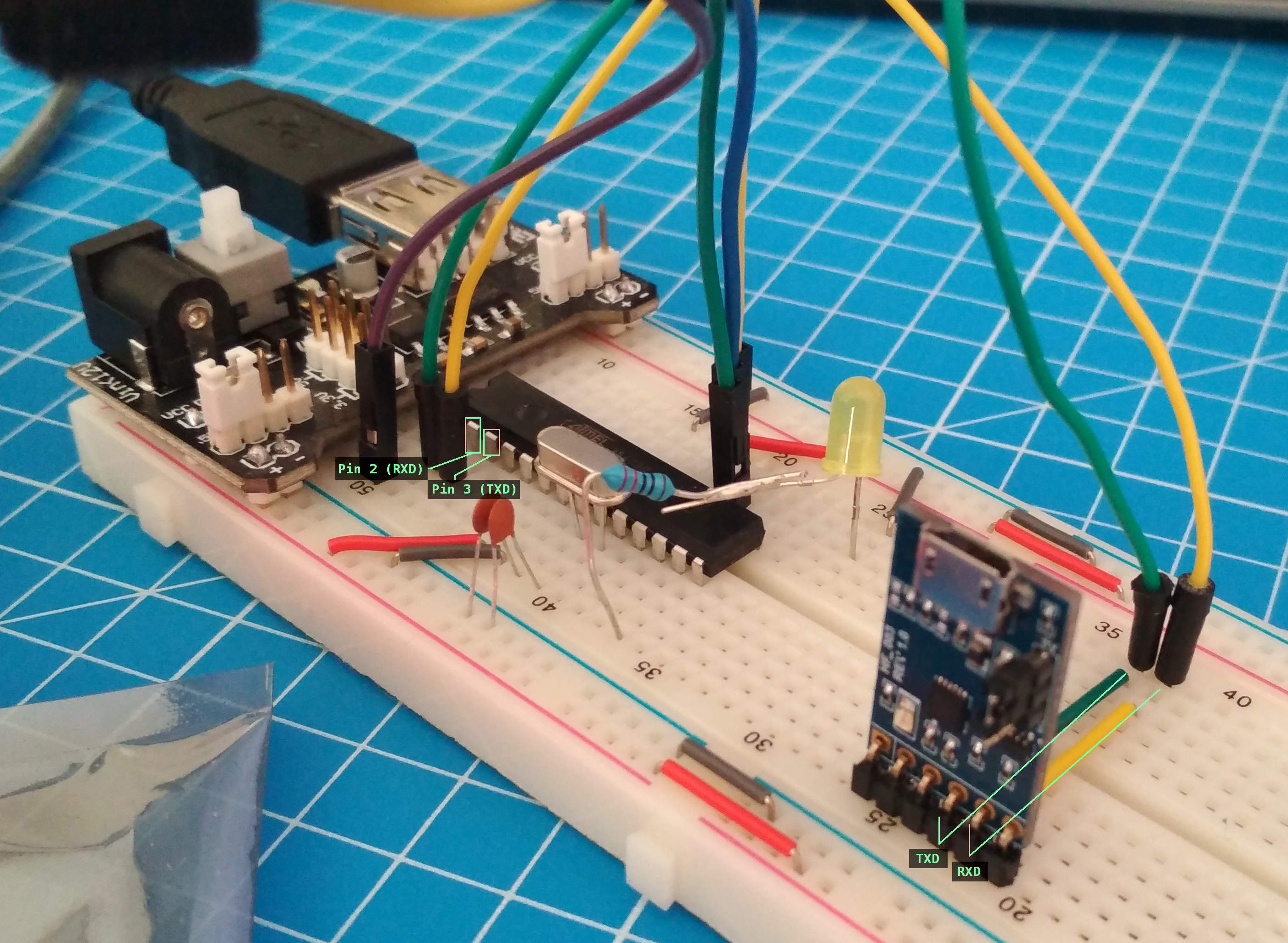
Note that two pairs of green and yellow wires have been used for the
RXD
and TXD pins. This was simply to make the board connections easier to see in the
photograph.
It's now necessary to configure the USART on the microcontroller, and start printing messages to the serial
console. In order to do this, we need to make some decisions as to the parameters we're going to use for serial
communication, and then work out which registers we need to use in order to actually configure the hardware.
The first parameter we need to decide upon is the transfer speed that will be used. This is known
baud rate, and is expressed in bits per
second. A baud rate of 9600 has been a common convention for low power serial
devices for many years, and is sufficient for our needs.
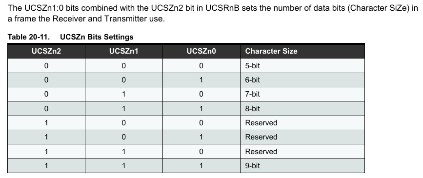
The next parameter we need to decide upon is the size of a single character in bits. There is very little reason
to use anything other than 8 bits per character, as we can match these to the
8
bit bytes used on almost all existing computer hardware.
The next parameter we need to decide upon is whether we'll include parity bits in the stream.
Parity bits
are an error detection mechanism that can detect transmission errors due to noise and interference. For
simplicity, we won't use parity bits.
Reading the datasheet section on the USART registers, on page 200, shows us that there are three 8-bit control
registers (UCSRnA, UCSRnB and
UCSRnC), one 16-bit register to specify the baud rate (
UBRRn), and a 16-bit register for sending and receiving data (UDRn). The
datasheet is written in a style where the register names include a lowercase
n
that denotes the nth instance of the register in question on the microcontroller.
The larger microcontrollers have multiple USART devices, and so you will see
UCSR0A, UCSR1A, UCSR2A,
and so on. On the ATMega328P, however, we only have on USART device, so the only registers we will see are
numbered at 0.
Jumping ahead to the register summary on page 621, we can immediately extract the following C definitions in the
same manner as we did for the
I/O ports
and timer registers:
7.5.7. USART Registers
volatile uint8_t * const UCSR0A = (volatile uint8_t *) 0x00c0;
volatile uint8_t * const UCSR0B = (volatile uint8_t *) 0x00c1;
volatile uint8_t * const UCSR0C = (volatile uint8_t *) 0x00c2;
volatile uint8_t * const UBRR0L = (volatile uint8_t *) 0x00c4;
volatile uint8_t * const UBRR0H = (volatile uint8_t *) 0x00c5;
volatile uint8_t * const UDR0 = (volatile uint8_t *) 0x00c6;
Inspecting the datasheet for the UCSR0A register shows us that we don't need to
touch the register for the initial setup, but we will need to use it during transmission. For example, we're
required to check the UDRE0 bit (bit 5) before we attempt to
send any data.
Looking at the datasheet for the UCSR0B register indicates that we will need to set
several of the bits in order to configure the transmission parameters we decided upon, so let's do that first.
Firstly, we need to enable the transmitter by setting bit
TXEN0
(bit 3) to 1. In order to select 8-bit characters, we need
to set bits in both the UCSR0B and
UCSR0C
registers:
We also need to calculate the value that will be placed into the
UBRR0
register in order to set the baud rate. The table on page 182 gives the equations that describe how to get from
a baud rate in bits per second, to a value suitable to be inserted into the
UBRR0
register:
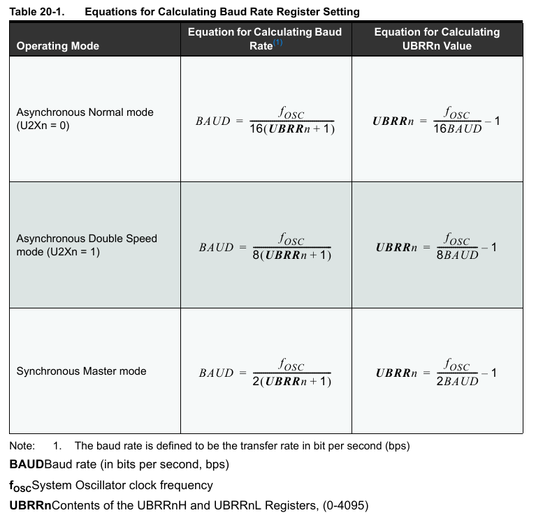
We can encapsulate this definition in a function:
7.5.14. Baud Calculation
static uint16_t
usart_ubrr(uint32_t cpu_clock_hz, uint32_t baud) {
  return (cpu_clock_hz / (16 * baud)) - 1;
}
Evaluating usart_ubrr(16000000, 9600) yields 103,
which matches the value in the table on page 199. We can now put together all of the initialization code:
7.5.16. USART Init
static const uint8_t TXEN_BIT = 0b00001000;
static const uint8_t UCSZn0_BIT = 0b00000010;
static const uint8_t UCSZn1_BIT = 0b00000100;

void
usart_init(uint32_t baud)
{
  /*
   * Configure the baud rate based on a 16mhz clock.
   */

  const uint16_t ubrr = usart_ubrr(16000000, baud);
  *UBRR0H = (ubrr >> 8);
  *UBRR0L = ubrr & 0xff;

  /*
   * Enable the sender.
   */

  *UCSR0B = TXEN_BIT;

  /*
   * Specify 8-bit bytes.
   */

  *UCSR0C = UCSZn0_BIT | UCSZn1_BIT;
}
The process for sending a single character over the USART interface is fairly simple. We wait for the
UDRE0
bit in the UCSRA0 register to become set to
0
by the underlying hardware, and then we place the character we want transmitted into the
UDR0
register. This can be encapsulated into a function, and we can add another function that allows for
sending entire strings:
7.5.18. USART Transmission
static const uint8_t UDREn_BIT = 0b00100000;

void usart_put_char(uint8_t data) {

  /*
   * Wait for the transmission buffer to become empty.
   */

  while ((*UCSR0A & UDREn_BIT) == 0)
    ;

  *UDR0 = data;
}

void usart_put_string(const char *str)
{
  const char *ptr = text;
  for (;;) {
    if (*ptr == 0) {
      break;
    }
    usart_put_char(*ptr);
    ++ptr;
  }
}
With these changes made, we can now update our Blink program to send messages on startup and each time the LED
is turned on and off.
7.5.20. Blink USART
#include <stdint.h>

volatile uint8_t * const UCSR0A = (volatile uint8_t *) 0x00c0;
volatile uint8_t * const UCSR0B = (volatile uint8_t *) 0x00c1;
volatile uint8_t * const UCSR0C = (volatile uint8_t *) 0x00c2;
volatile uint8_t * const UBRR0L = (volatile uint8_t *) 0x00c4;
volatile uint8_t * const UBRR0H = (volatile uint8_t *) 0x00c5;
volatile uint8_t * const UDR0 = (volatile uint8_t *) 0x00c6;

static const uint8_t TXEN_BIT = 0b00001000;
static const uint8_t UCSZn0_BIT = 0b00000010;
static const uint8_t UCSZn1_BIT = 0b00000100;
static const uint8_t UDREn_BIT = 0b00100000;

static uint16_t
usart_ubrr(uint32_t cpu_clock_hz, uint32_t baud) {
  return (cpu_clock_hz / (16 * baud)) - 1;
}

void
usart_init(uint32_t baud)
{
  /*
   * Configure the baud rate based on a 16mhz clock.
   */

  const uint16_t ubrr = usart_ubrr(16000000, baud);
  *UBRR0H = (ubrr >> 8);
  *UBRR0L = ubrr & 0xff;

  /*
   * Enable the sender.
   */

  *UCSR0B = TXEN_BIT;

  /*
   * Specify 8-bit bytes.
   */

  *UCSR0C = UCSZn0_BIT | UCSZn1_BIT;
}

void usart_put_char(uint8_t data) {

  /*
   * Wait for the transmission buffer to become ready.
   */

  while ((*UCSR0A & UDREn_BIT) == 0)
    ;

  *UDR0 = data;
}

void usart_put_string(const char *text)
{
  const char *ptr = text;
  for (;;) {
    if (*ptr == 0) {
      break;
    }
    usart_put_char(*ptr);
    ++ptr;
  }
}

volatile uint8_t * const TCCR1B = (volatile uint8_t *) 0x0081;
volatile uint8_t * const TCNT1L = (volatile uint8_t *) 0x0084;
volatile uint8_t * const TCNT1H = (volatile uint8_t *) 0x0085;

static const uint16_t ticks_per_second = 15625;

void
pause (void)
{
  // Select a /1024 prescaler.
  *TCCR1B = 0b00000101;
  *TCNT1H = 0;
  *TCNT1L = 0;

  for (;;) {
    uint16_t time = 0;
    time |= *TCNT1L;
    time |= *TCNT1H << 8;

    if (time >= ticks_per_second) {
      return;
    }
  }
}

volatile uint8_t * const PORTB = (volatile uint8_t *) 0x0025;
volatile uint8_t * const DDRB = (volatile uint8_t *) 0x0024;

int
main (void)
{
  *DDRB = 0b11111111;

  usart_init(9600);
  usart_put_string("start\n");

  for (;;) {
    *PORTB = 1;
    usart_put_string("led on\n");
    pause();
    *PORTB = 0;
    usart_put_string("led off\n");
    pause();
  }
}
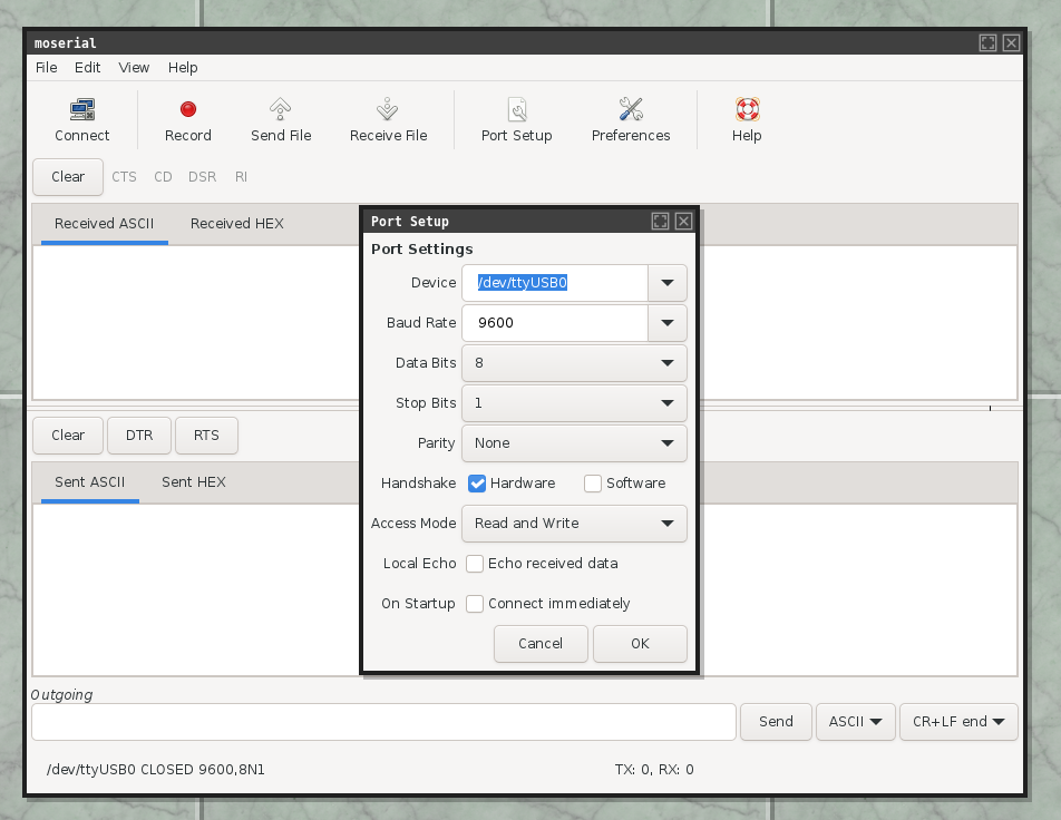
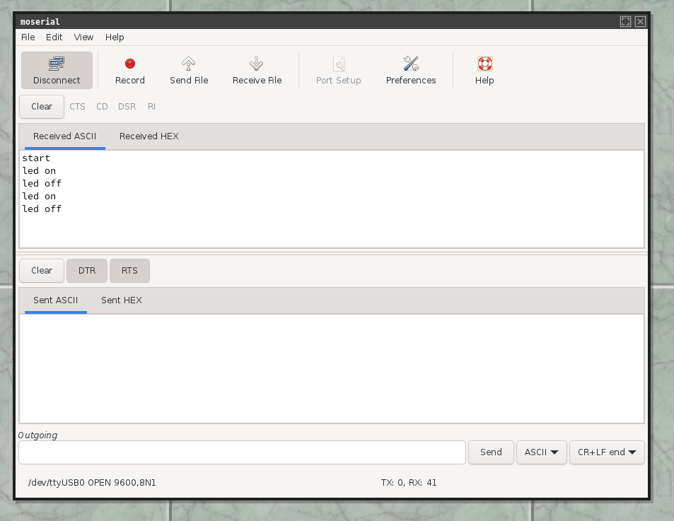
When the LC234X is connected to a Linux workstation, the operating system will typically create a
tty
device with a name similar to /dev/ttyUSB0. It's possible to use any serial
console application to observe data being sent over the LC234X connection. One such application is
moserial, shown here receiving
data from the serial connection: